Cat.#040954400
 |
||
 |
The hallmark of the Crispin
Tilting Disc Check Valve is its superior design and function. Its concept provides the
most efficient and solid approach to flow reversal. The characteristics of the design
produce a head loss lower than that of most any other check valve made. The main idea behind the "Tilting Disc" Check Valve is its 55 degree slanted seat position. Unique to the "TD" design, this seat positioning provides extremely high efficiency and operability. |
|
Seating
The Crispin Tilting Disc Valve accomplishes full flow opening by having the disc pivot
or "tilt" in the flow of the media. Swing check valves move the disc out of the
flow by displacing the seat disc to the upper portion of the valve. By pivoting the disc
in the flow, the opening stroke range of the Tilting Disc Valve is far less than that of
other valves, reducing the opening and closing times critical to controlling flow reversal
and reducing water hammer.
The seating surfaces of the seat ring and disc are machined to an angle of approximately 20 degrees, providing more clearance right up to closing while reducing seat wear and improving sealing properties.
Opening Stroke
The key to the valve’s efficiency is its "in the flow pivot." When the
velocity is sufficient to open the valve, the pivot pin clearance allows the valve to
un-seat without sticking.
Once open, the tear-drop like design of the disc keeps it stable and un-fluttering in the flow. Meanwhile, full opening is achieved through only 40% stroke from the seated position.
Disc Pivoting
The seat disc opens and closes the valve by pivoting on two fixed pivot shafts
attached to the disc from either side of the body. Replaceable pivot bushings of a
different material hardness in the disc are the actual pivot points, and are located
almost 1/3 of the way down the disc, leaving 2/3 of the disc weight below. The resulting
counter balance effect closes the valve quickly yet limits slamming.
Pivot Pin Clearance
Since the "tilting" of the disc on a 1/3, 2/3 split puts part of the disc
through the seating area, there must be a small clearance around the pivot bushing and
pivot shaft. The top of the disc seats from the opposite direction as the bottom. The
built in clearance allows the disc to "float" into place at final seating.
Longer Laying Length
Having the disc "tilt" in the media gives the valve a longer laying length
or face-to-face dimension than other valves. This extended length provides a very smooth
body and disc contour thus reducing the turbidity common to other designs.
Increased Flow Area
With a flow area that is at least 40% greater than the nominal valve size, the tilting
disc check valve has a much lower head loss than a conventional swing check valve. It has
three times higher flow in many cases.
Field Replaceable Seat
The Crispin Multiplex "TD" Series Tilting Disc Check Valve is manufactured
with ease of field maintenance in mind. The seat is replaceable in the field without the
need for special tools or equipment, thus reducing valve down time.
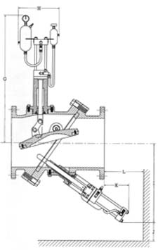
External Position Indicator
Directly attached to the disc itself through one pivot shaft, this indicator serves as
an easy and positive reference in determining whether the valve is open or closed.
Dual Inspection Ports
An inspection port is located on the top and bottom side of the seat for examination
of normal wear. It also serves as the mounting point for optional dashpots.
By-Pass Piping
Optional by-pass piping is available for needs such as slow line filling and
controlled line drain.
Dashpots
Designed to control the opening and closing speeds of the valve, optional dashpots
help eliminate line surges and valve wear. Available with top and bottom mountings, they
are field adjustable and can often be added later. Both utilize a high quality hydraulic
piston cylinder to control disc movement.
Bottom Side Dashpot
This dashpot features a rounded end shaft that projects through the 55 degree angled
seat ring. It is not physically attached to the disc itself. It therefore cannot control
the rate at which the valve opens, but rather controls the last 10% of the closing stroke.
Upon closure, the disc strikes the rounded end rod connected to the piston in the hydraulic cylinder. Oil in the cylinder is displaced into the accumulating tank. The rate at which this oil is displaced is the rate at which the valve closes during that last 10% of movement. This oil displacement is adjustable through the use of a needle valve. After closure, when the valve reopens, a spring pushes the rod back into position so that it is ready for the next cycle.
Top Side Dashpot
With top side dashpots, the piston is connected directly to the disc via a shaft and
links in order to control both the opening and closing of the valve. This operation’s
two chamber cylinder also has two separate accumulator tanks. When the valve opens, oil is
displaced into the larger of the two chambers and can be adjusted as above. This controls
the full stroke of opening.
During closure, however, the design of the two chamber cylinder allows closing to be broken into two stages. The first stage of the closing stroke is much quicker due to the pressurized air cushion in the larger tank. This air expands and forces the oil back into the chamber faster, creating pressure against the piston and closing the valve quicker.
The actual closure rate of this first stage is achieved by a combination of adjustments of the two accumulator tanks—oil out of the large tank into the top chamber of the cylinder and oil out of the bottom chamber of the cylinder into the small tank. The second or final stage of closure is controlled by a small internal valve and an oil flow channel that controls the last portion of the oil flow into the smaller accumulator. Adjustment of this valve allows the disc to have a final cushion" at the end of the closing stroke.
Additional Product Notes
- All valves are tested to AWWA Specification #C-508.
- Discs and disc seats in valves 10" and smaller are one-piece design.
- All valves are available in Class 125 and 250 grey iron, as well as Class 150 ductile iron. Consult factory for additional material options.
- Valves should be located a minimum of three pipe diameters from the discharge of a pump.
- Crispin warrants all materials and workmanship from one year of purchase.
- Disc position indicators are standard on valve sizes 16" and larger, as well as with any added dashpot option.
- Inspection ports are optional on valve sizes 6" thru 10".